In terms of developing a payment gateway, there is no doubt that both the security and the stability are extremely important. A typical banking system is expected to keep 100% uptime and perfect security together. Otherwise a downtime or a security vulnerability can cost astronomical prices.
In addition to that, the security and the uptime are legal necessities for the payment systems. Almost all regulators no matter which country, publish similar directives and legislations for the security standards and the uptime ratios of banking systems.
It is not a big challenge to build a super secure system with 100% uptime for an expert team. However it is impossible without applying the correct network topology and the architecture. By this point you may ask that: the Reapplication of topology models which are already running in thousand of banks may not sound like as hard as that much. The point is that: none of them uses a standard topology nor architecture. But all of them have to be compatible with the standards of payment processing. That makes each project unique and painful and that’s why I’m posting this blog.
Today in this post, I’ll share you the top fundamentals and outer borders of a network topology for typical payment system (and/or payment gateway).
The 3 Layered Topology
The whole system should run on servers distributed in at least three layers. You may be familiar with this concept if developed a web based system. One of the key differentiation of this topology is keeping the client side software out of these three layers which are usually shown in the first layer by the developers.
The layers should not be confused with the software developing concept names like MVC (model view controller). The layers in here are representing the layers of servers sets. Of course the software running on the servers must have layers too.
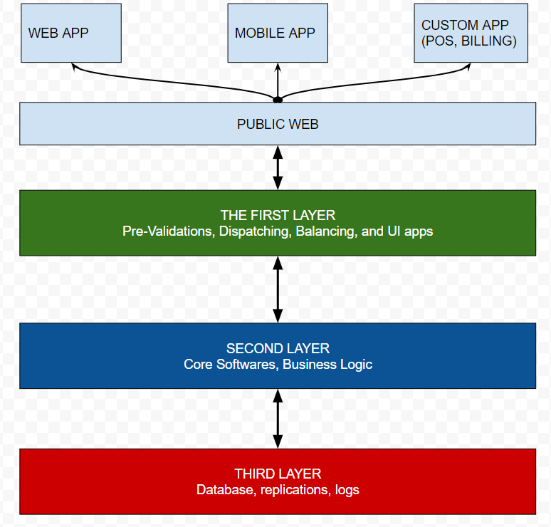
1.) The first layer is the application layer that should be able to connect public internet and the second layer. First layer usually hosts only UI/UX components. Pre-validation of API services are also should be in this layer.
An important point about the first layer is the DNS. Since the servers in this layer can be accessible, they have public hostnames (domain/subdomain) names.
The load balancers (LB) and disaster recovery (DR) active reactions are usually set by router devices in network. But the first layer also can hosts them as well.
2.) Second layer is the core-software layer which has no access to the public internet but only the servers located in first layer and the third layer. It is an internal bridge of the topology.
The 2nd layer typically hosts the API services, codes of logic algorithms, controllers and models. Eventually, those are server side running codes and should never be accessible from the public internet. Of course it is not possible to access to the source codes server side languages. So the servers can defend source codes anyway. But the objective is the protection of the servers. Not the codes. In other words, the first layer will be a defending wall to keeping 2nd layer always live in cases of network attacks.
Since the 2nd layer is going to have connections to the 3rd layer which has the data, it has to be checked and tested perfectly by IT security experts. Security team must keep that in mind: there is a possibility of accessing this layer if the 1st layer hacked. So it must have some self-defending abilities but I can not dive the details for this post.
3.) The third layer (a.k.a. “the data layer”) is the deepest and most sensitive layer that contains the database(s). The key point is, this layer can never has connections with anywhere except the 2nd layer. The data layer is going to be the final target for the hackers. Only this layer contains what they want to get and bank has to protect. At least, putting some basic precautions to this layer just like “limiting of data exporting out of the layer” can be life saver for the worst case. Fortunately, It is possible with simple network restrictions too. (Most of RDBMS provides the limiting configurations as well)
(Here will be a post about how the “limiting the data exporting” works as a precaution)
Despite to the Figure 1 does not seem like too complicated to be a big challenge, the realizing this network topology can to be very confusing and complex in real cases. Since the payment systems has to be integrated with other payment institutions like PF/PSP/Bank/CC Network e.t.c. to complete a processing of transaction may establish tens of connections at the network layer.
When it comes to a “CC payment flow” it sounds like a basic connection between card holder and a bank. Because it is just an credit card data attached to an order goes to bank then returns a result. Isn’t it ? Well, in fact that runs on multi-dimensional interactions between client side software, card holder, card network, authentication bank, payment service provider e.t.c. The system must apply all the rules about network security without any exception while providing all those connections and integrations.
The Payment Flow
According to W3C a payment flow should be like:
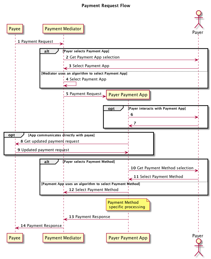
Unofficial Draft 20 November 2020
Actually, none of the payment gateway projects that I’ve been lead yet, was less complicated than the W3C’s flow.
As mentioned, only the first layer connects to the public internet. That means everything shown at Figure 2 runs only on the 1st layer. So it doesn’t contain the flows between bank layers and external integrations.
The integrations with other institutions better to be connected from the first layer too. The 2nd layer is also acceptable for some integrations at exceptional cases like another system of the same bank that working in the same datacenter.
There are thousands of exceptions to be faced with the network when it is integrated with other payment gateways. The payment gateways may redirect the transaction for the authorizations of other systems and that may redirect another. The more integrations the more rules on the network.
The topology in figure 1 is a simplified representation shown the layers as simple as possible. It is going to be more detailed in real cases. But the number of layers and the connection principles will be same.
Within the post I’ve tried to compile a post by merging some of my personal experiences from several projects. I know that the post can be better when has more details but less targets. I wish it helps someone.
Please let me know If you have any question or contribution. Just drop me a line by using the contact form or the comments section.
I’ll share more post about the TECH part of the fintech.